
I’ve been trying to control my garden railroad by computer for years. I have a test layout in my living room. I’ve installed the Java Model Railroad Interface (JMRI) and now have it running 4 trains. Each train can be run independent of the others. Yes you can cause a train wreck (Uncle Fester would be proud.)
My passenger train is drawn by a Rügen steam loco from LGB. The decoder was installed when it was built around 2000. I haven’t been able to modify the control variables, so it has 3 running speeds: creep, fast and fly off the track.
My trains are controlled by DCC decoders (see Tony’s DCC Primer for a good introduction to Digital Command Control.) I’m using Digitrax command stations and stationary decoders. I can control all my trains and turnouts through a hand held controller.
JMRI gives me the ability to control everything through a computer. It will run on Windows, Apple, Linux or even Raspberry PI computers. I’m running on OpenSUSE linux.
Every DCC decoder has a number of Control Variables (CVs) that adjust things like speed curves and which controller buttons affect the lights and sound, etc. JMRI’s DecoderPro was written to read and set them from a graphic interface on a computer.
The first thing DecoderPro does is to try to identify which decoder is in this locomotive. Each decoder has CVs to identify the manufacturer and version number. Unfortunately for me, LGB decoders (made by Massoth) all have the same manufacturer number and the same range of version numbers. So I had to guess.
Other modules include PanelPro which creates panels like what is used by a dispatcher in the real world.
This is what I see when I run the trains.
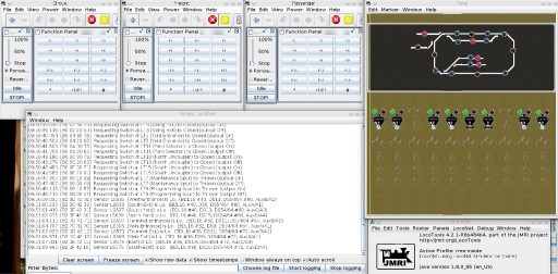
In the upper left are the throttles for each of the trains. Each controls the direction and speed of a train and can be used to blow the horn or turn the lights on/off. Below them is a trace of the DCC commands.
An animated diagram of the layout is in the upper right. The bright red lights are supposed to be occupancy indicators. The dark blue indicators are connected to physical sensors which are activated when a locomotive with a magnet passes over them. The sensors are reed switches normally used by home alarm systems for doors. When one is activated it can turn occupancy lights on or off and control turnouts as needed.
The levers below the layout diagram control the turnouts. When they are changed, the physical turnout is changed as is its representation in the diagram above.
The next phase will involve DispatcherPro. It will let me set up a schedule for all the trains and run them as a real railroad would.
The end goal is to move all this out to the garden railroad in the back yard and let the trains run with minimal intervention.